Simulation
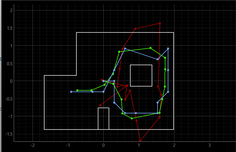
The simulation results were similar to those from lab 10. The localization prediction matched the true pose closely while the odometry data was frequenctly inaccurate, showing the robot moving outside the boundaries of the map.
Mapping
Artemis Code
To complete the robot trajectory, I reused the mapping code from lab 9 only changing the number of samples I was collecting to be 18 and the angle increments to 20 degrees. The videos of the robot's rotations are included below.
Perform_Observation_Loop
My observation loop reuses the bluetooth commands from lab 9. I first call my START_MAPPING command which performs the 360 degree robot rotation and then activate my notification handler to receive time of flight and yaw data. The data transmission is triggered by MAP_DATA command. On the python side, the handler waits for 36 readings, (18 tof and 18 yaw) and then stores the data in sensor_data.csv. I also had to turn the function asynchronous to be able to wait for the data to be transmitted before calling the localization function.
Perform_Observation_Loop
Artemis Code
A helper function get_sensor_readings reads the contents of the sensor_data.csv file and converts the tof and yaw data into numpy arrays suitable for the localization function.
(-3,-2,0)
plot.png)
ToF Measurements
tof.png)
Yaw Angles
yaw.png)
Belief
bel.png)
The prediction matched the true position very well, only being off by in the predicted orientation by 10 degrees. I did not expect the results to match the true position that well. The high accuracy of the results is likely due to the fact that at (-3,-2) robot sees two seprate obstacles and 3 close walls, which makes the location very disinguashible.
(0,3,0)
plot.png)
ToF Measurements
tof.png)
Yaw Angles
angles.png)
Belief
bel.png)
The result at (0,3) was very similar to the result at (-3,-2) in that the predicted position was very close to the true position. However, the predicted orientation had a larger error of 30 degrees. Similarly to the previous position, the high accuracy is likely due to the robot seeing large portions of the map in terms of obstacles and walls. The yaw at each point in the orientation was consistently off by 1-3 degrees, which could have contributed to the larger error in the predicted orientation.
(5,-3,0)
plot.png)
ToF Measurements
tof.png)
Yaw Angles
ang.png)
Belief
bel.png)
The estimated location of the robot at (5,-3) was off by 0.305 meters in the x-direction and 0.305 in the y-direction. The prediction here was worse than at the previous two locations because both corners of the right wall are generally less disinguashible compared to other locations in the map. It is also possible that the TOF sensors were moving during the robot rotation, leading to shorter readings and an estimate that is closer to a wall.
(5,3,0)
plot.png)
ToF Measurements
tof.png)
Yaw Angles
angles.png)
Belief
bel.png)
The estimated location of the robot at (5,3) matched the true position in the x-direction, but was off by 0.304 meters in the y-direction. Similarly to the last positon, the right top corner also did not produce very accurate results. The estimated position was again predicted to be closer to a wall ( in this case an obstacle wall) compared to the true location. The discrepency in the y estimate could be attributed to the slight displacement of the robot closer to the obstacle during the 360-degree rotation.
Resources
I referenced Jack Long's code for ideas on how to pass the bluetooth data to the localization functions.