Lab 2: IMU
Set Up
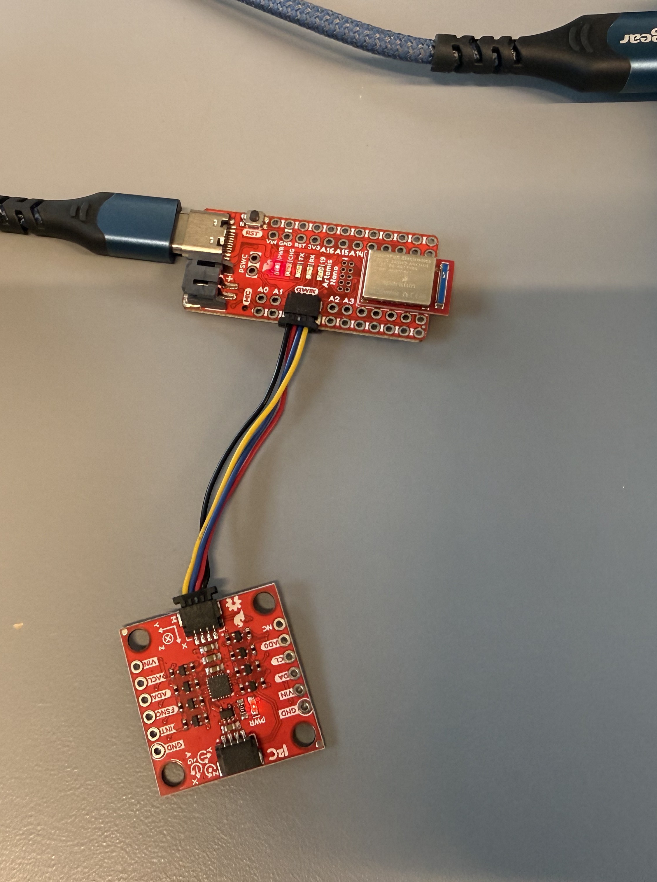
AD0_VAL represents the last bit of the I2C address used by the IMU and also the read/write flag. On our system the bit should be set to 1.
Running Example Code
In the video, you can see the acceleration data showing 1000 mg corresponding to the 1 g of acceleration due to the force of gravity. As the orientation of the IMU changes, the 1000 mg value transfers between the axis. The gyroscope data shows zero degrees when the IMU is flat and then shows a changing value as it is rotated since the gyroscope measures the rate of change of the angle.
Accelerometer
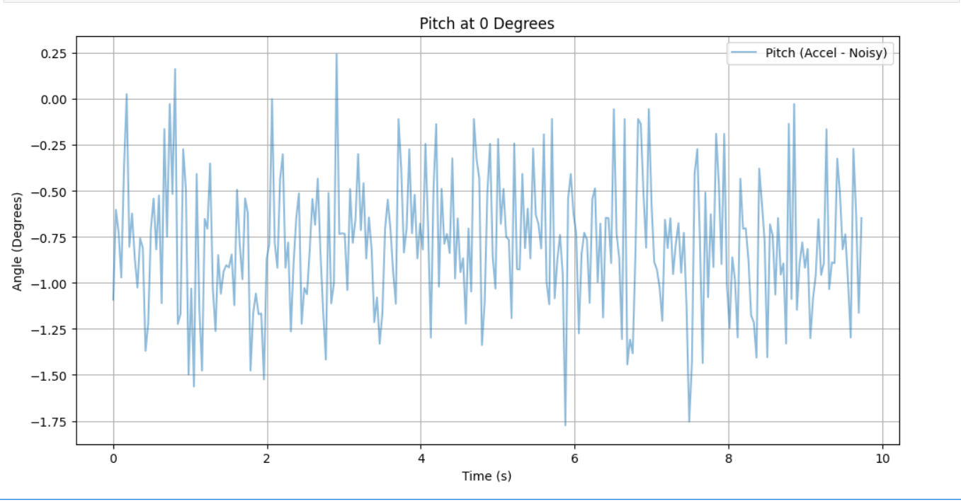
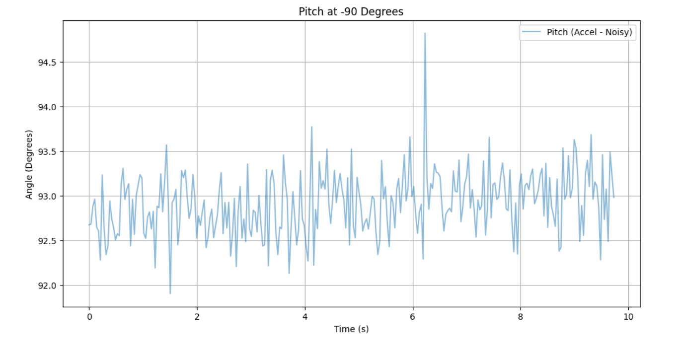
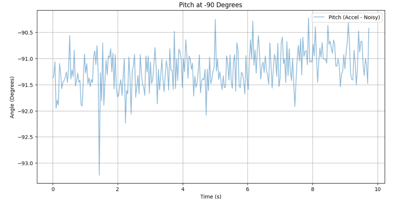
Pitch
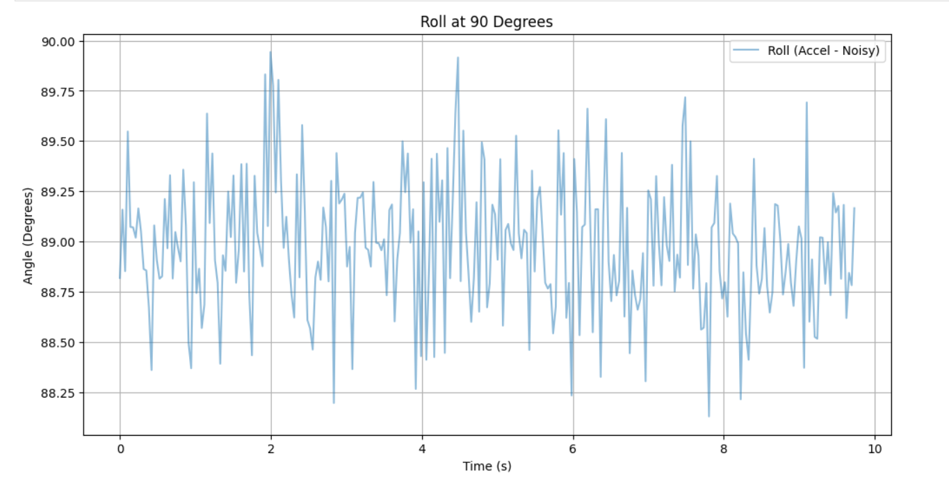
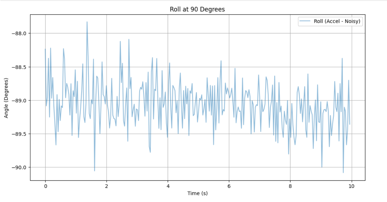
Roll
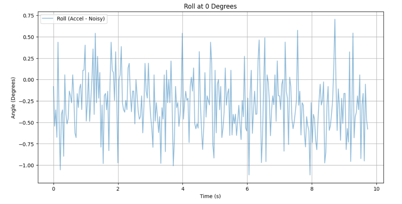
Accuracy Discussion
The accelerometer data did not exhibit a stationary offset, deviating between 0 to 20 mg offset between readings. Performing the two-point calibration, I found that the average offset for the z-axis acceleration was 17.8 mg, -3.37 mg for y-axis, and 2.5 mg for x-axis. Hence, the accelerometer data is fairly accurate. Adjusting the accelerometer data utilizing the offset and the scaling factor did not appear to produce significantly more accurate or precise data.
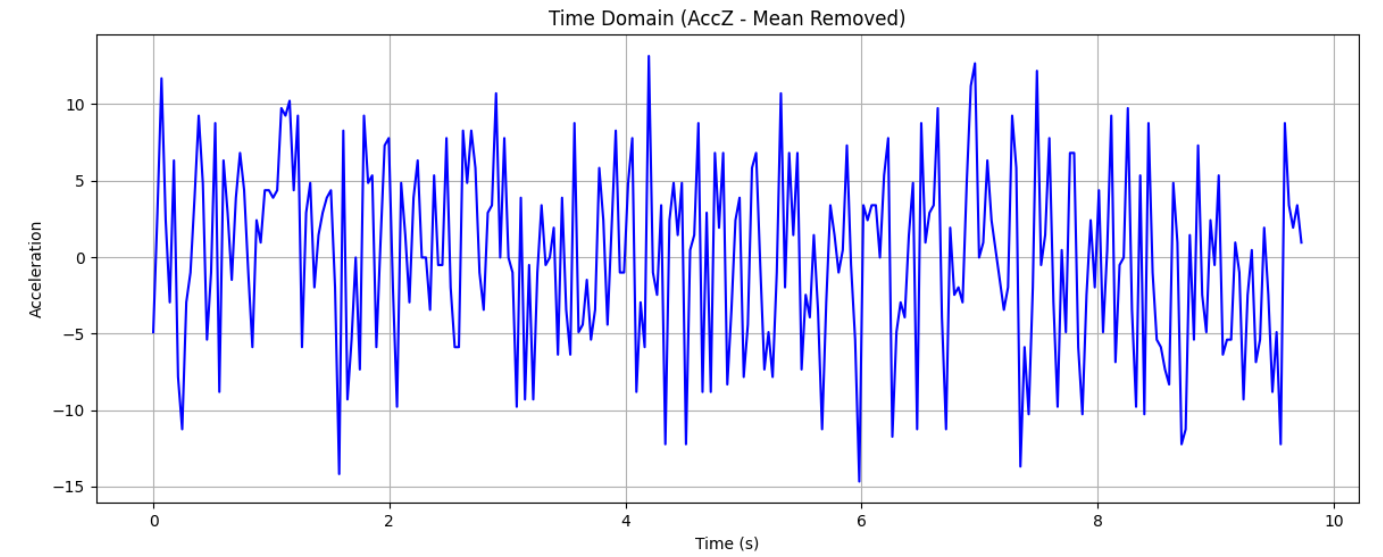
FFT
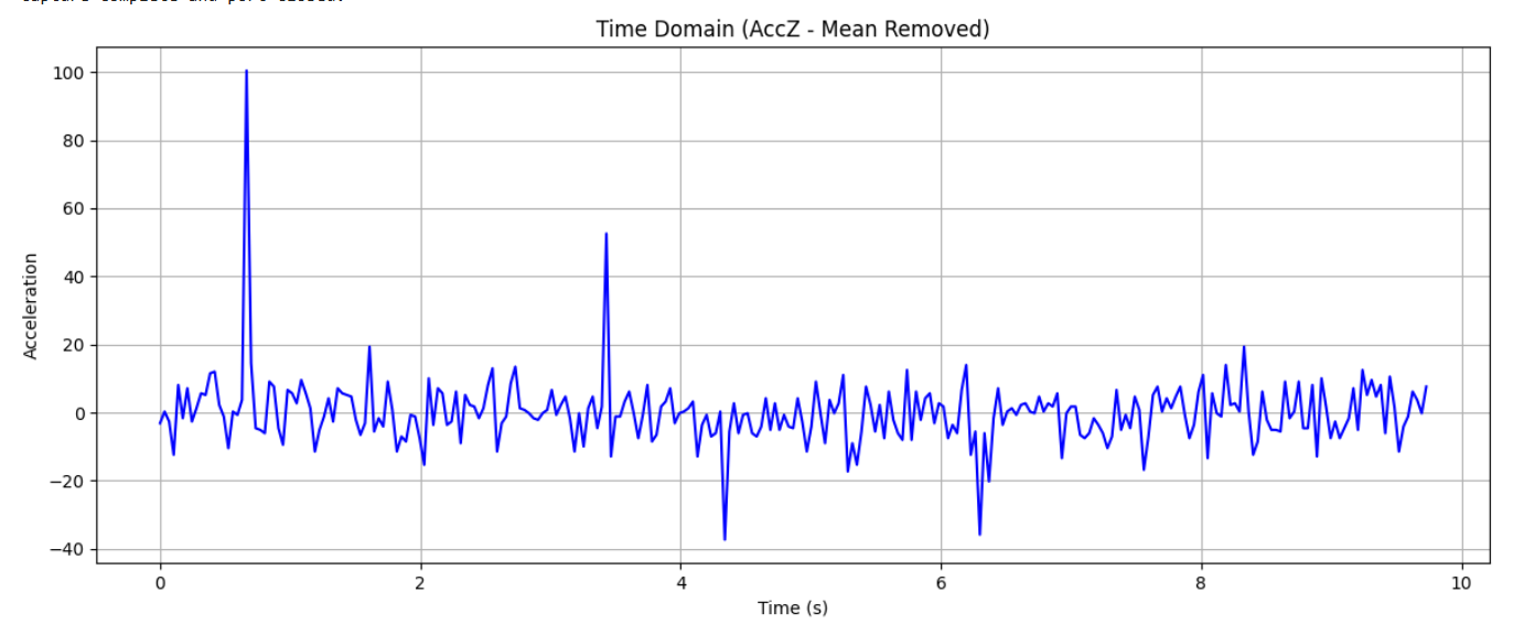
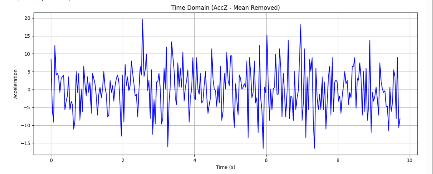
Baseline Reading
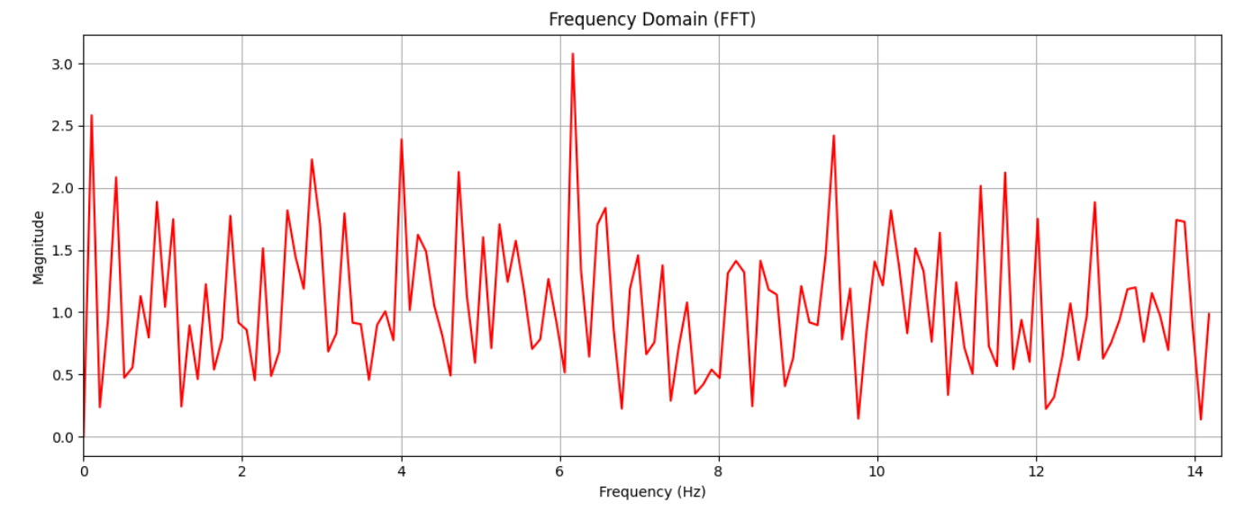
Reading on a Vibrating Table
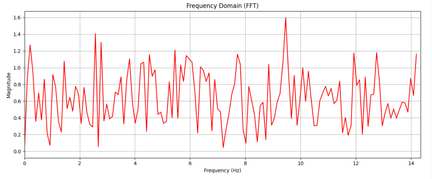
Reading Nearby RC Car
Filtering
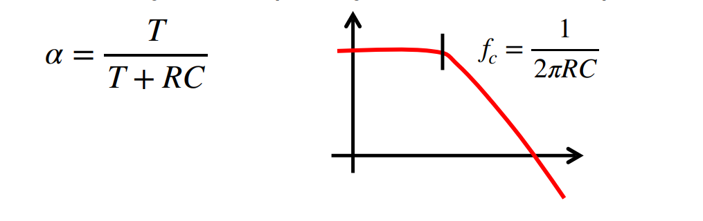
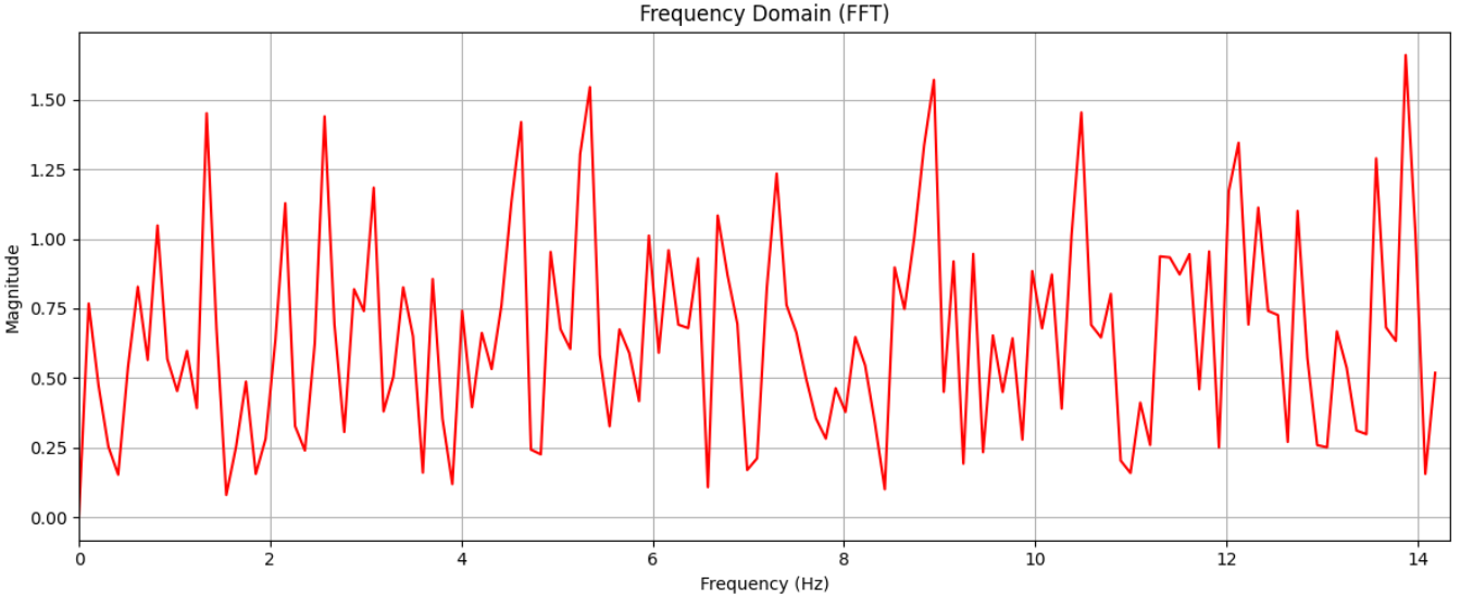
From the regular reading and the reading with the rc car showed a peak at about 9Hz. The table vibration plot showed a peak at about 6 Hz. With this information, I chose the cutoff frequency of 9 Hz to eliminate the noise at both of the aforementioned frequencies. Using the equations provided in class, and substituting 30 ms as the sampling rate, the alpha value was calculated to be 0.629.
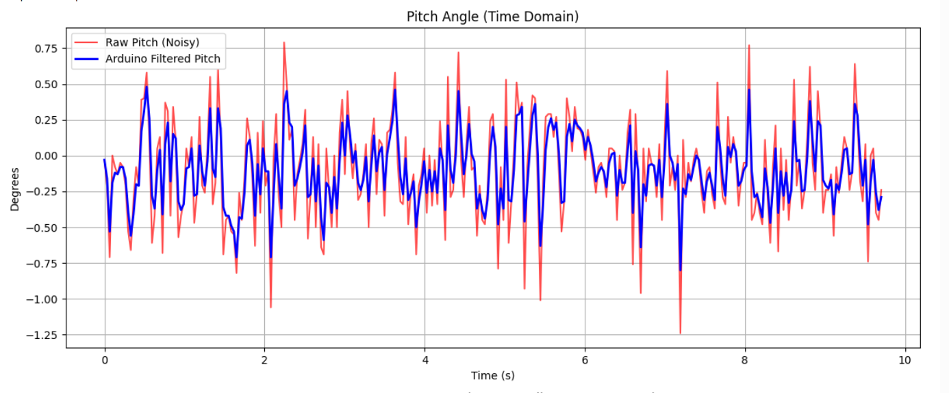
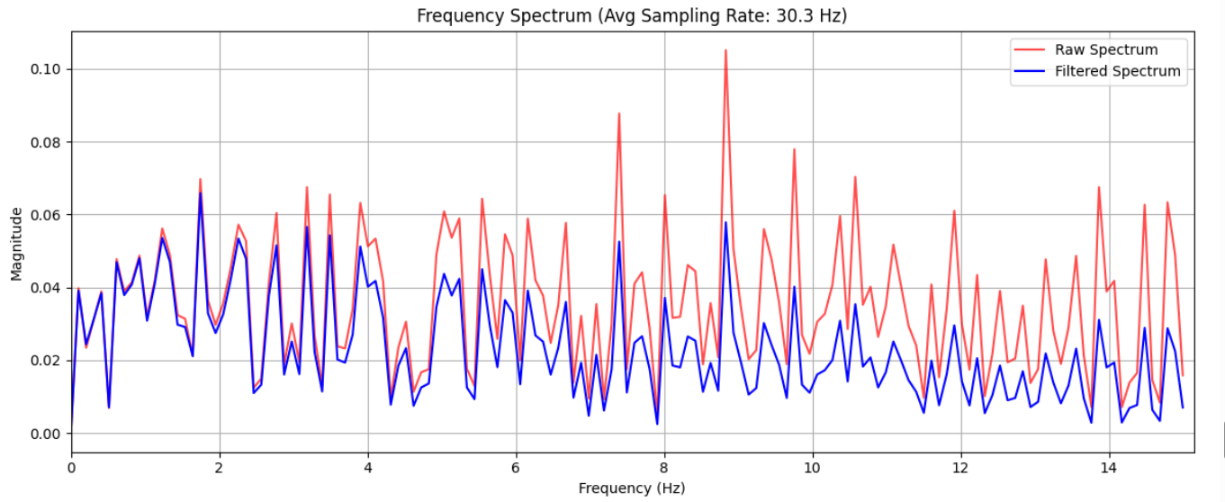
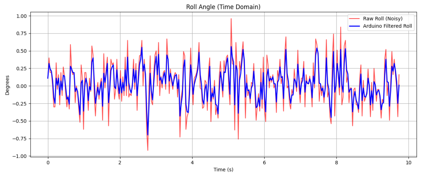
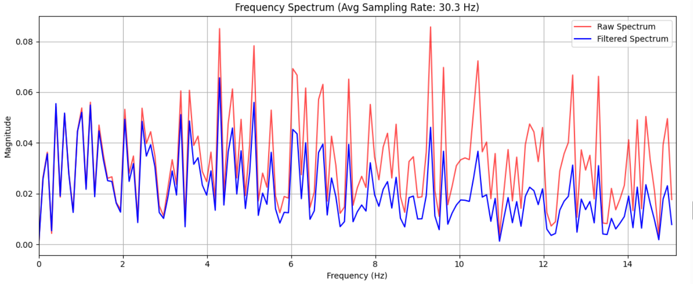
The results showed that the low pass did decrease the noise, however, the alpha value was not optimal and could be further tuned for better performance.
Gyroscope
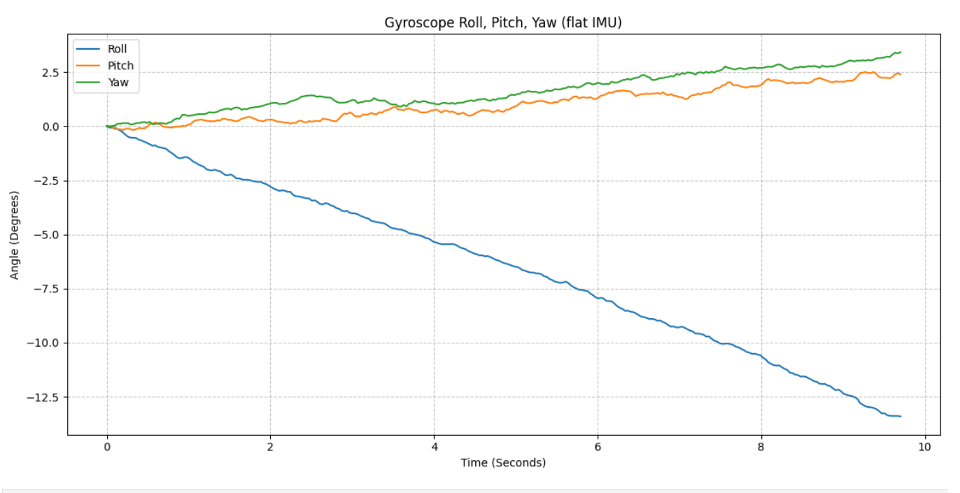
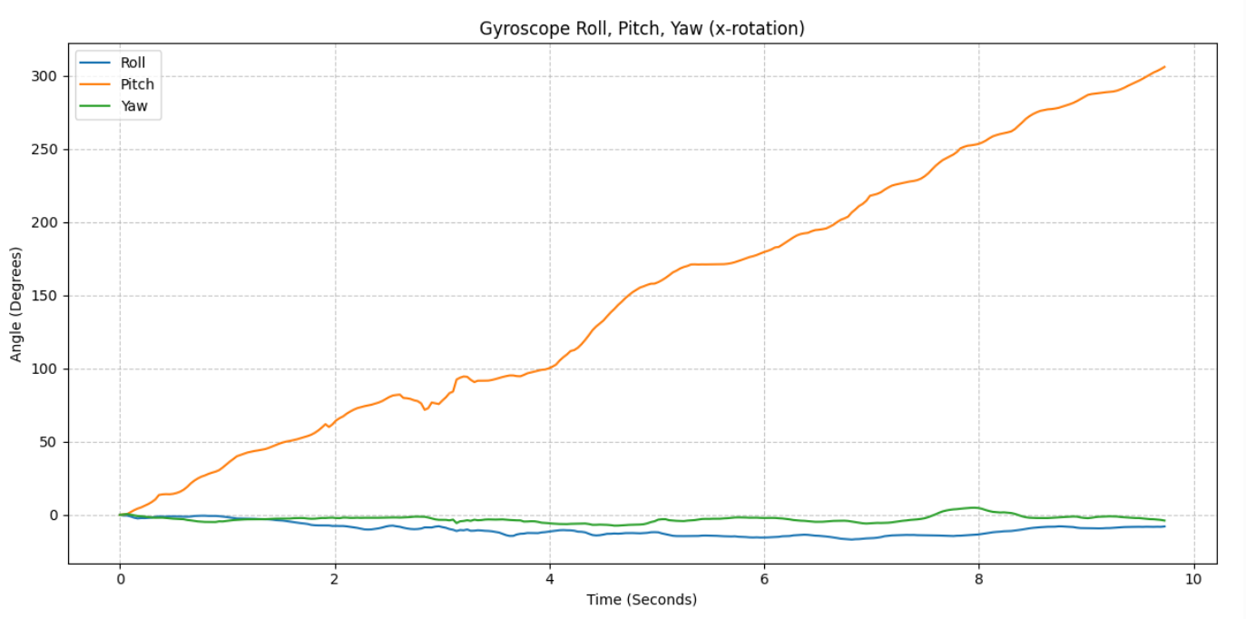
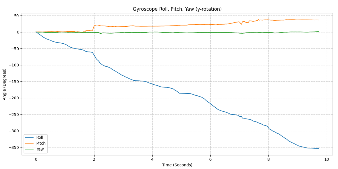
In comparison with the accelerometer data, the gyroscope data is significantly less noisy. However, it also experiences significant drift over time. The drift is most observable in the flat IMU plot where the angle that should stay at approximately 0 degrees drifts.
Complementary Filter
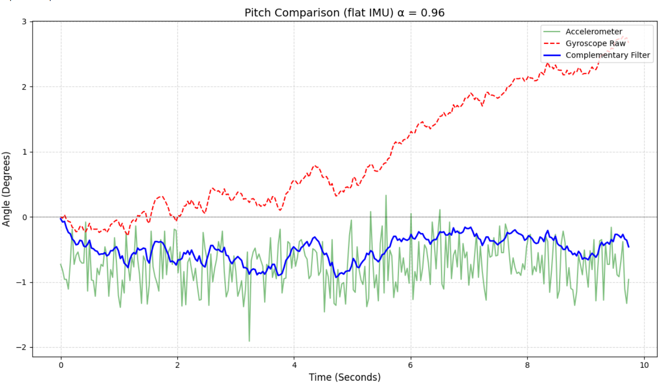
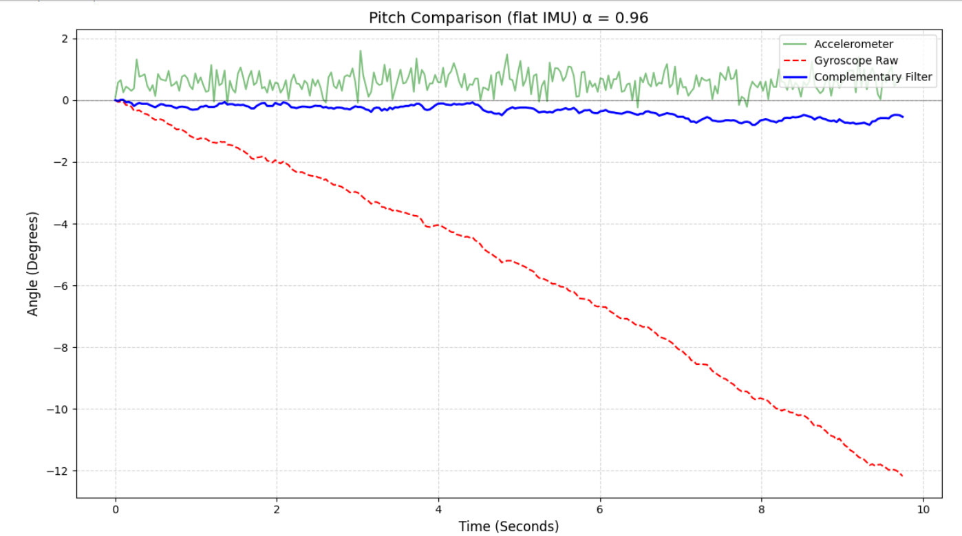
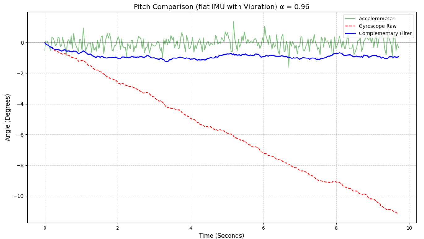
The output from the complementary filter showed significantly less drift for both roll and pitch data seen in the plots above. After testing a few alpha values to use with the filter, I chose an alpha of 0.96 where the value of the gyroscope is trusted 96%. The last plot was recorded on a shaky table, showing that the filter is not susceptible to vibrations from the environment.
Sample Data
Data Storage
I think the more effective choice for storing accelerometer and gyroscope data would be store them separately in order to limit the amount of data that needs to be transmitted over bluetooth. Since pitch and roll data can be calculated from both sensors, it is unlikely that we will be using all the data unless we are doing full sensor fusion. Keeping the data separate will allow us to only transmit the data necessary and in the case that we need both of the sensors, it would be easy to match the data together using the timestamp.
I am storing the IMU data in floats because they have a good balance between precision and memory usage. Integers take up little memory but lack precision while doubles are too precise for our purpose. Strings would be too memory intensive and not necessary for storing numerical data.
Consider the memory of the Artemis; how much memory can you allocate to your arrays? What does that correspond to in seconds?
5 Seconds of IMU Data
Main Loop
The video shows the transmission of only the z-axis acceleration data from a flat IMU, sent using the float characteristic. The main loop on the Artemis does not run faster than the IMU is able to provide new data because I'm not seeing any repeated data in my arrays. If we allocate about 100kB of Artemis's 384 kB of RAM to arrays, we would be able to store about 3571 IMU samples if we are populating 7 arrays of floats (time, 3 acceleration values, 3 gyro values). At my current sampling frequency of 30 Hz, that would amount to 119 seconds of data.
Stunt
Observations
From testing the car, I was able to observe that it can move a little less than 1 kitchen tile, with the minimal application of forward speed. That test also showed that even at very small distances, the car has a slight drift, not following a straight line. I was also able to see that it is fairly easy to complete a 180-degree turn in both directions by applying the forward motion and turn simultaneously. Lastly, I observed that it is quite easy to flip the car over if you drive into a stationary object. My controller also lost contact with the car twice when I was testing, so there are definitely range limitations in terms of communication.
Resources
I used both Jack Long's and Lucca Correia's webpages as references for formatitting the FFT graphs and used Gemini for help with FFT code. The low-pass filtering alpha equation and visual are from class notes.