Lab 4: Motors and Open Loop Control
Schematic
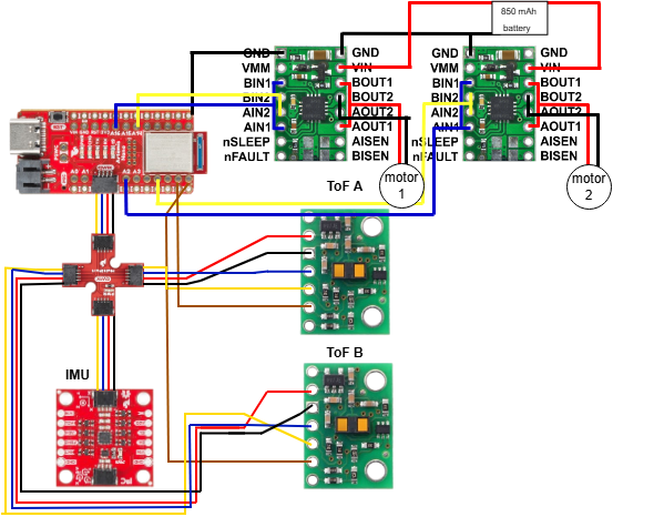
Battery Discussion
It is important to have separate batteries for the motors and the Artemis board because the motors consume a lot of current in comparison to the other, lower-power components. Separating the motors from the rest of the sensing system allows us to avoid voltage drops in the system ensures that the motors are able to draw the current they need without affecting the performance of the rest of the system.
Oscilloscope Set Up
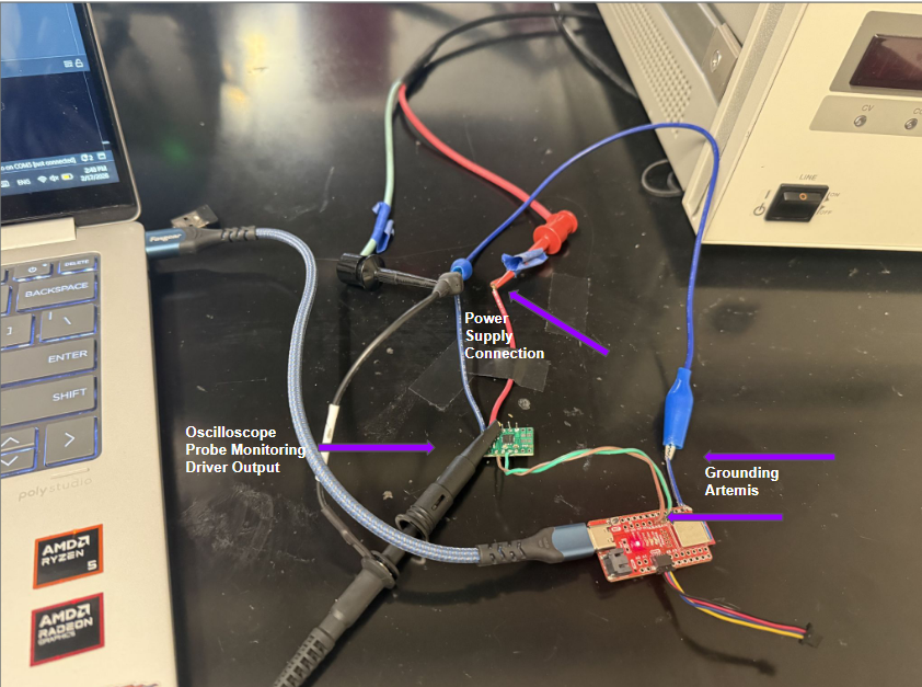
Prior to connecting the motors to the motor driver, I used the oscilloscope to verify that the PWM signal from the Artemis board was producing an appropriate response at the output of the motor driver. I connected the oscilloscope probe both to the to the output pin of the Artemis board and the output pin of the motor driver. The image above shows the oscilloscope connection to the output of the motor driver.
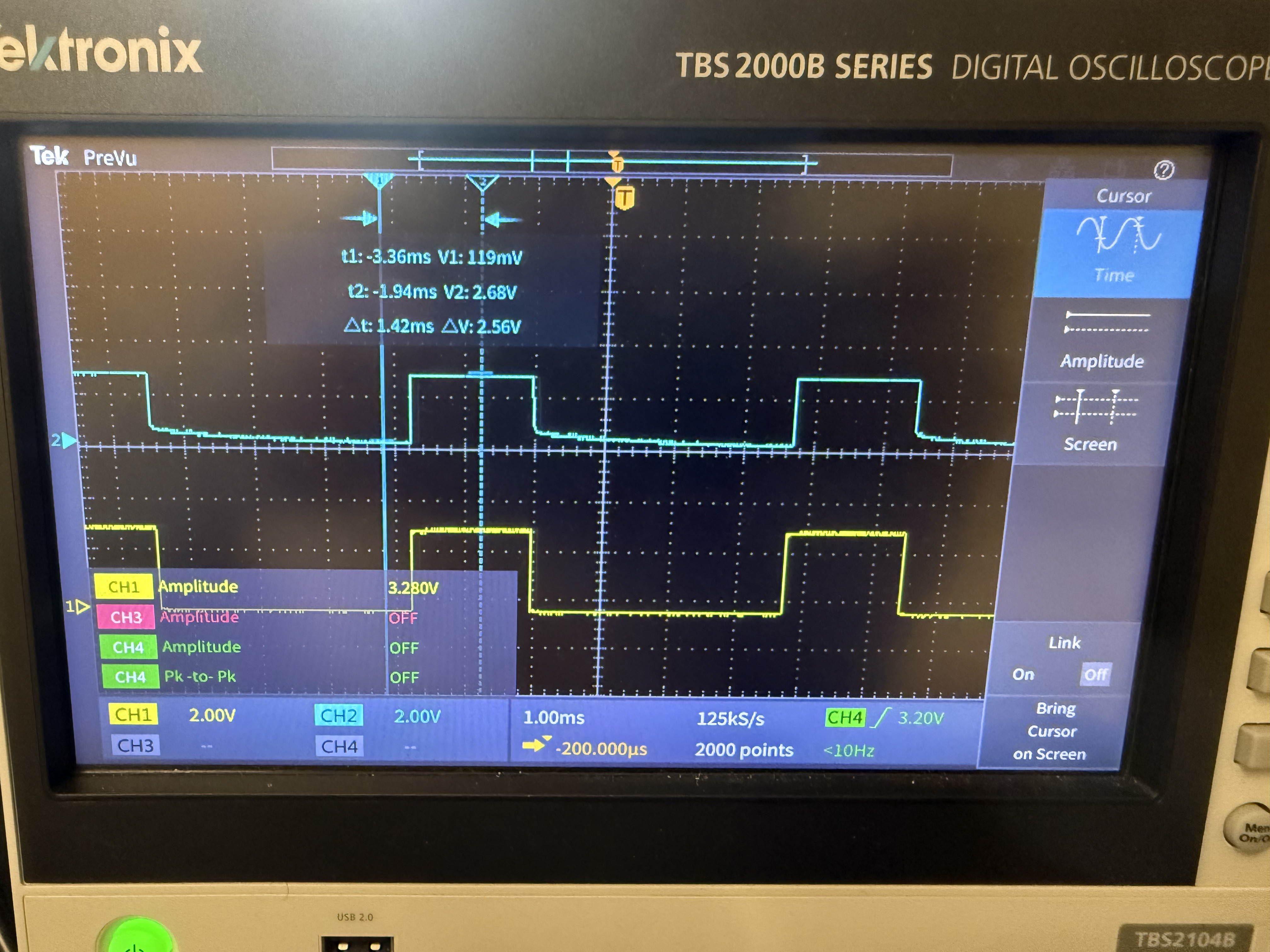
In the following oscilloscope image, the yellow signal is the Artemis output with a 50% duty cycle or a pwm value of 127 in the 8-bit range of 0 to 255. The blue signal is the output of the motor driver.
The above video shows the PWM inputs and the motor driver response at changing duty cycles.
Power Supply
A reasonable setting for the power supply would be a voltage of at least 3/3.7V and a current limit of about 500mA with a single motor as the load.
Single Motor Testing
Forward
Reverse
The above videos show the results of testing a single motor powered by a power supply. The analog pin pair (A14, A15) was used to control the motor with a pwm value of 70 being written to pin A15 via the analogWrite function to make the motor spin forward. For the reverse direction, the same pwm value was written to pin A14. A more detailed example is shown in the code snippet in the next section.
Two Motors Powered by the Battery
Forward
Code
Artemis Code
Reverse
Code
Artemis Code
The above videos and code snippets show the results of testing two motors powered by the battery. Pin pairs (A14, A15) and (A2, A5) were used to control the two motors with a pwm value of 70 being written to pin A15 and A2 via the analogWrite function to make the motors spin forward. For the reverse direction, the same pwm value was written to pin A14 and A5.
Final Set Up
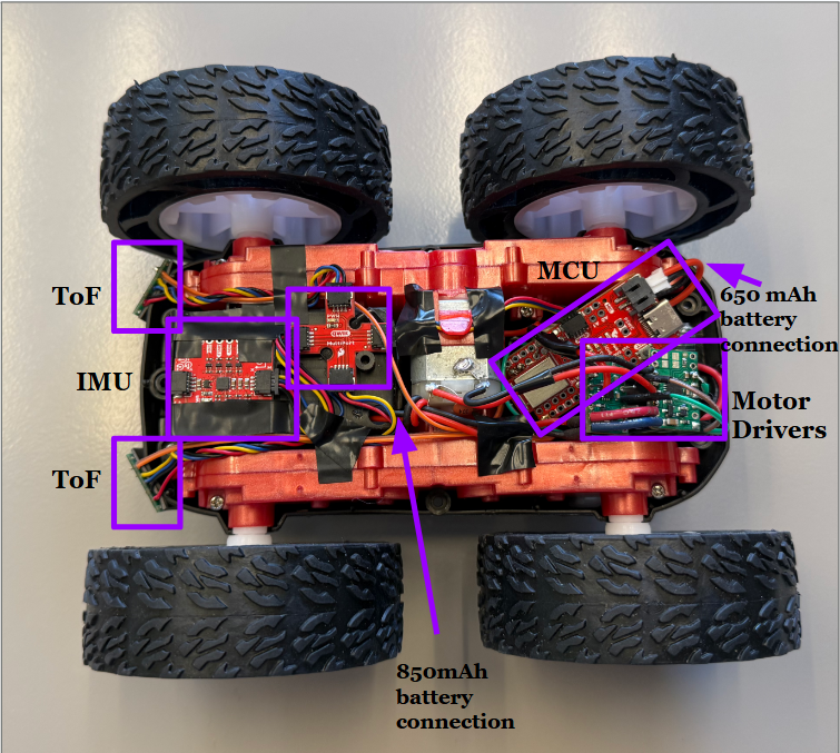
In the final car set up shown above, the 2 TOF sensors and the IMU are positioned at the front of the car. The Artemis board along with the motor drivers and the 650mAh battery are positioned at the back of the car. The two motors are powered by the 850 mAh battery located in the battery housing.
Calibration
During the initial open loop testing, the car was turning to the right, indicating that the left motor was spinning faster than the right motor. I was able to achieve a straight line motion with a pwm value of 63 for the left motor and a value of 90 for the right motor, indicating a calibration factor of about 1.43 for the right motor. The straight line test is shown below.
PWM Limit
The RC car was able to overcome static friction for a forward motion with a left motor pwm value of 30 and a right motor pwm value of 32. The video below shows the car moving at these pwm values.
The RC car was able to perform an on-axis rotation with a pwm value of 110 applied to both the right and the left motor in opposite directions. However, a rotation at these values takes a long time to complete and a more reasonable starting value for an on-axis rotation would be 150 or higher. The video below shows the car rotation with a 110 pwm value applied to both motors. .
Open Loop
Open Loop Drive Code
Artemis Code
analogWrite Frequency
The PWM frequency generated by the analogWrite functions on many popular microcontrollers is less than 1 kHz which is a fairly low frequency. However, since the motors are appropriately responsive to the PWM signal, this low frequency does not appear to be an issue for the performance of the car. One advantage of manually configuring timers is that we would be able to increase the frequency of the PWM signal which could potentially lead to smoother motor performance and more controlled motion. However, since the car is able to perform reasonably well with the default PWM frequency, I do not see a strong need to increase the frequency of the signal.
PWM Motion Limits
I experiementally determined that once the RC car is in moving, I can decrease the pwm value from a value above 30 (value to overcome static friction for straight-line motion) to 26 and the car is still able to keep moving forward. The car was able to settle into a steady forward motion at a pwm value of 26 after 30 ms. The code snippet below shows my set up for testing this.
PWM Motion Limits Code
Artemis Code
Resources
I used Aidan Derocher's webpage to verify the schematic for the motor driver set up.