Lab 5: Linear PID control and Linear Interpolation
Pre Lab - Bluetooth
To use the PID controller, three new bluetooth commands were added to my code - START_PID, UPDATE_PID, and Send_PID_DATA. In order to be able to update the gains and the setpoint, all udatable variables are stored globally. Therefore, START_PID initializes the PID controller using the global gains set. UPDATE_PID receives new gains and the setpoint via the bluetooth command in the format: ble.send_command(CMD.UPDATE_PID, "0.0161|0.0075|0.0026|304.0"). Finally, Send_PID_DATA iterates through the arrays storing debugging data. On the python side, a single notification handler parses the incoming data for plotting and logging. All three code snippets are shown below.
START_PID
Artemis Code
Send_PID_DATA
Artemis Code
UPDATE_PID
Artemis Code
Frequency Discussion
Since both of my TOF sensors are mounted in the front, I am able to use both of them for updating recorded distances to the wall. When testing the frquency of the updated distances, I was getting a new value from either sensor A or B (both in short-range mode) about every 8-10ms, which is consistent with my results from lab 3. Since I am relying on only one of the sensors giving me an updated distance, the frequency of the updated reading ranges from about 100 to 125 Hz. The frequency of the main loop was only slightly higher at around 130 to 150 Hz due to the amount of computations being done in the loop.
Linear Interpolation
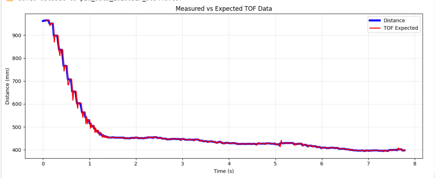
To implement linear interpolation for the distance data, I found the slope of the average of the two sensors and used it, in combination with time lapsed between readings, to estimate the distance at the next time step. A graph plotting the actual distance readings from the sensors and the linearly interpolated distance can be seen below. The linear interpolation matched the actual readings closely but experienced more extreme oscillations.
Lab Tasks
PID Implementation
To account for present, future and past errors, I implemented the full PID controller outputting a control effort based on the equation u(t) = Kp*e(t) + Ki*integral(e(t)) + Kd*derivative(e(t)). In the main Artemis loop, I am continuously calling the function pid_step which calculates the control effort based on the current error and the PID gains, then feeding the output to a motor control function. pid_step continuous to run storing the debugging data until the pid time interval has elapsed.
pid_step
Artemis Code
The control effort output by the PID controller was mapped to a range suitable for the motor PWM signal via the function map_effort_to_pwm(float effort). In this function a control effort of a 100.0 corresponds to the maximum PWM signal of 255.
map_effort_to_pwm
Artemis Code
Proportional Control
Prior to tuning the derivative and integral gains, I first tuned the proportional gain. I initially selected the KPe gain in tandom with pid effort motor mapping code. The starting distances being 2m to 4m would result in a maximum error of 3696 ( 4000 mm - 304 mm setpoint). Since in my motor mapping code, a control effort of 100 corresponds to a PWM signal of 255, I wanted to select a Kp gain that would result in a control effort of around 100 for the maximum error. Therefore, I started tuning the proportional gain with values of 0.05 and below since 100/3696 is approximately 0.027. I tuned the gain from a distance of 2.5 to 3 meters as those starting distances resulted in more overshooting at higher gains, eventully settling on 0.0161 as the gain that resulted in a good response without excessive overshooting at several starting distances.
Derivative Control
Implementing a derivative term further helped reduce the overshoot by aniticipating the future error based on the current rate of change of the error. Initial observations of the derivative term showed large spikes in data due to noise in the TOF sensor readings, so I implemented a low pass filter seen in the code snippet below. I chose to not eliminate derivative kick because I do not anticipate any large setpoint changes that would result in a large derivative kick.
Integral Control
The integral gain was tuned to helped close the gap between the car and the target at small distances by eliminating the steady state error. Intgeral wind up protection was also implemented to prevent accumulated integral error. (More details on the protection implementation and testing can be found in the Integrator Windup section below).
The final gain set up that worked for my system was Kp = 0.0161, Ki = 0.0075, and Kd = 0.0026.
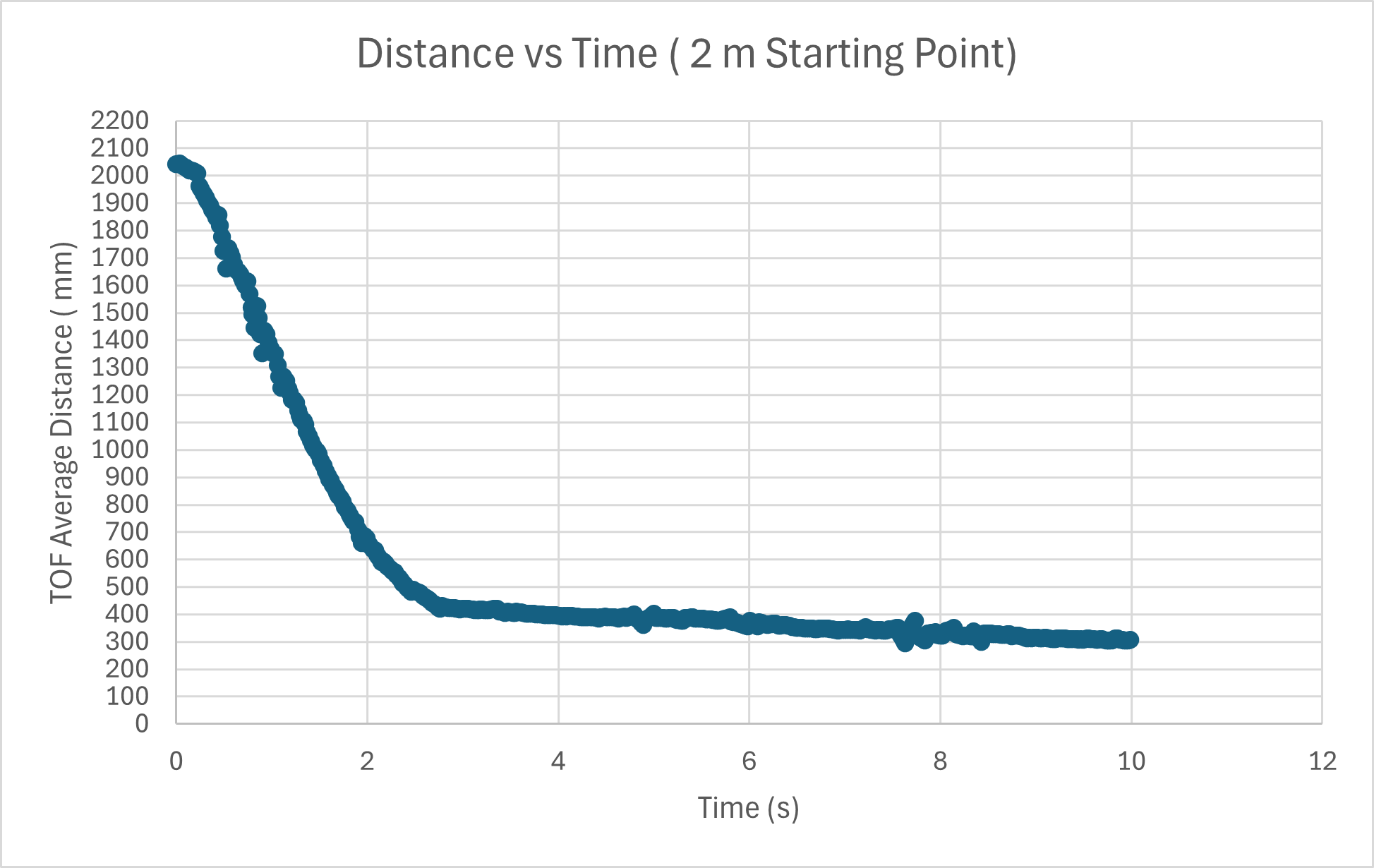
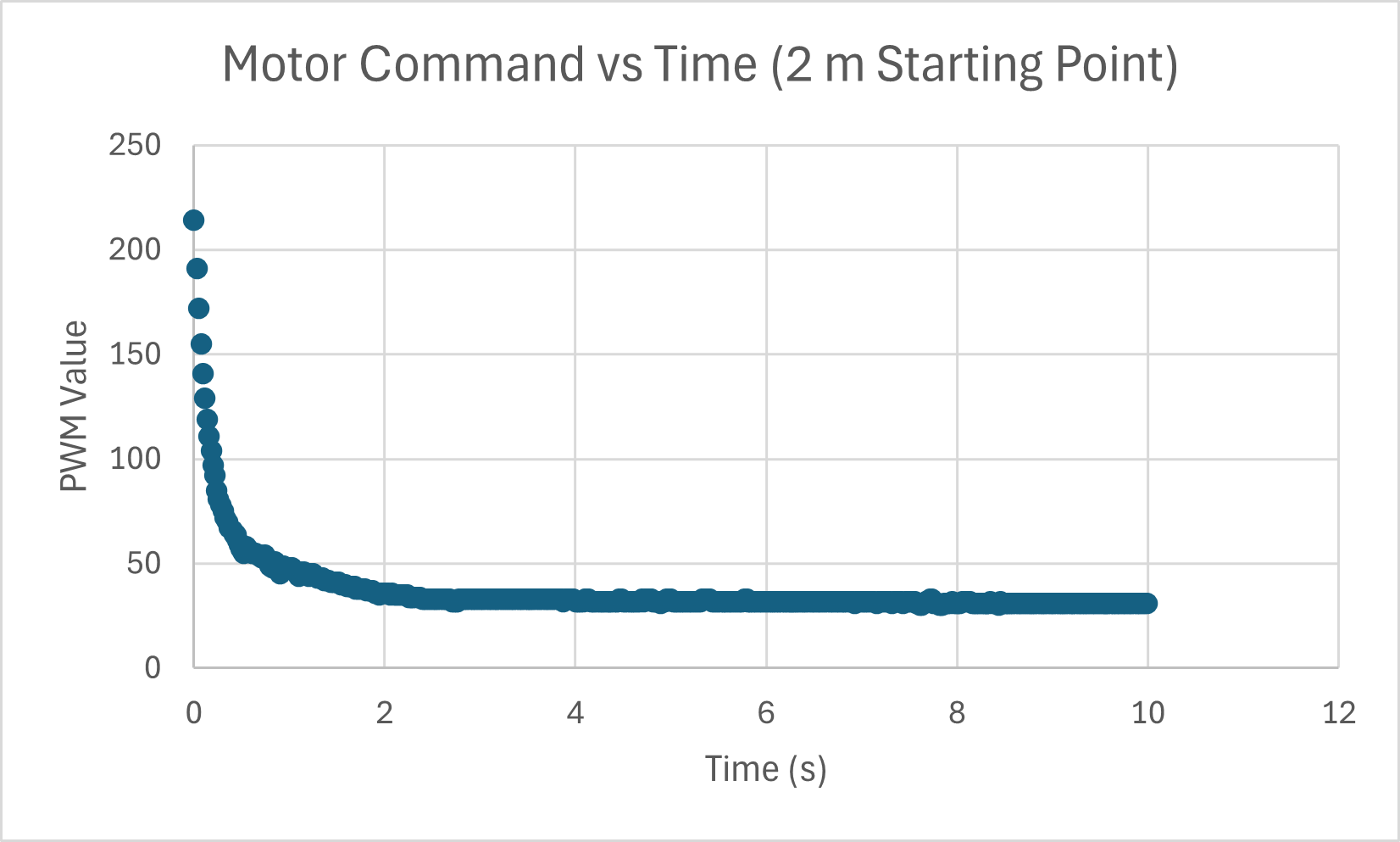
Test 1: 2 meter starting point
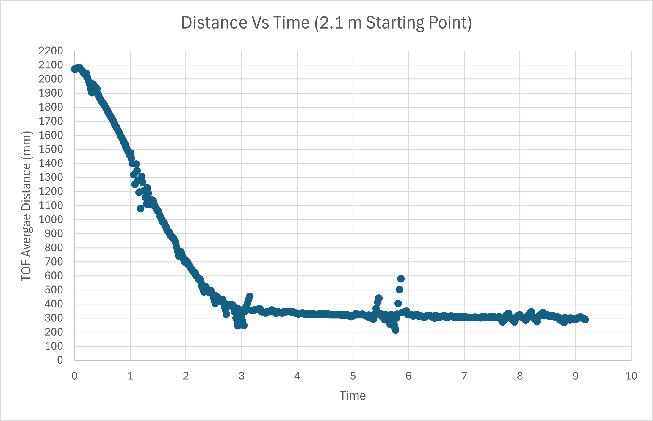
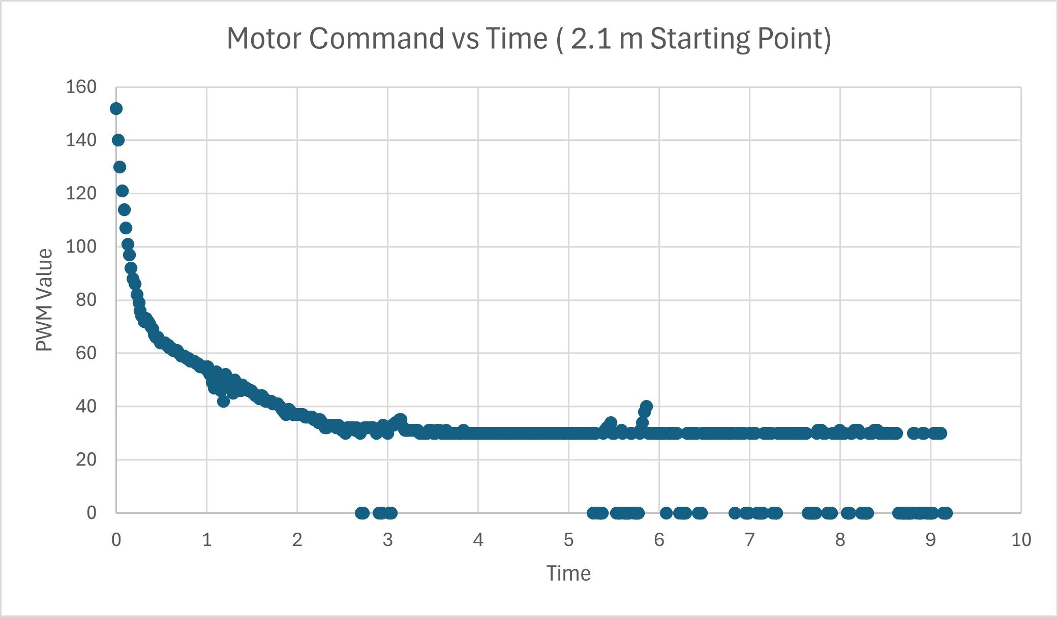
Test 2: 2.1 meter starting point
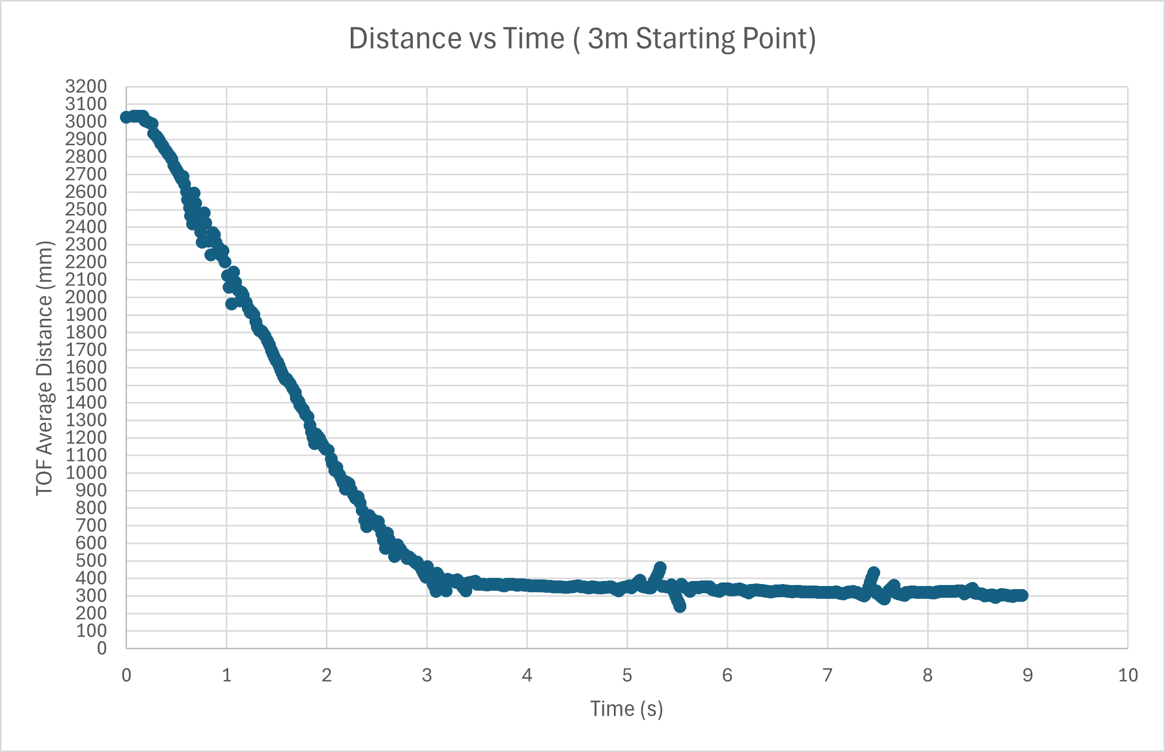
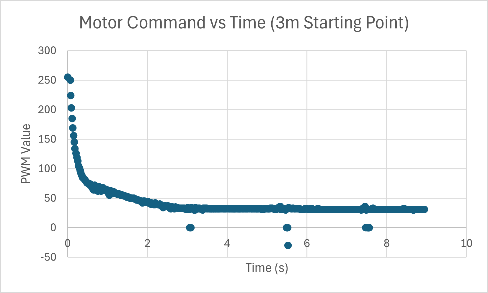
Test 3: 3 meter starting point
External Perturbations Test
Linear Speed
Based off the timing and TOF sensor data, the maximum linear speed of the car was calculated to be around 3.5 m/s. This was calculated by taking the distance traveled between two TOF sensor readings and dividing it by the time elapsed between those readings.
Integrator Windup
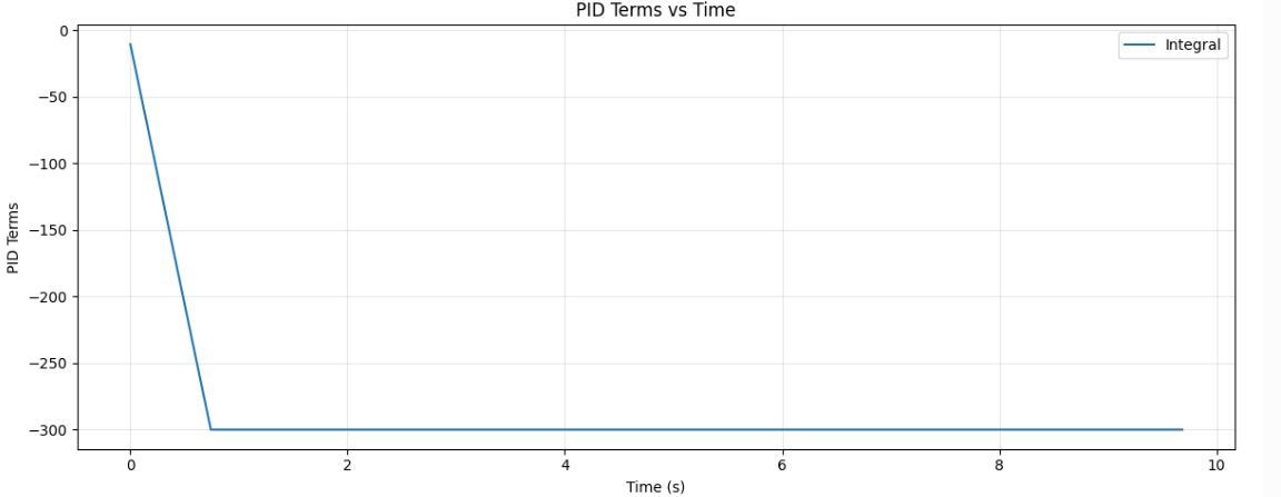
I implemented the integrator windup protection by constraining the possible value of the integral term as shown in the code snippet below. One reason for impelementing wind up protecting is to handle the scenario where the car is temporarily stuck or blocked by an obstacle. In such a case the integrator error would continue to accumulate while the car is not moving, resulting in a large integrator term that would be difficult to recover from. I tested the effectiveness of the protection by holdong the car in place for a few seconds and then releasing it. With the protection, the car was able to recover and move towards the target distance without excessive overshoot. The integral term graph below shows the integral term pluteauing at -300, which is the limit I set for the integrator term.
Artemis Code
Integrator Windup Test
Resources
I used Stephan Wagner's page as a resouce for seeing how to organize the PID controller code.