Lab 6: Orientation Control
Pre Lab - Bluetooth
To use the PID controller, three new bluetooth commands were added to my code - IMU_PID, IMU_PID_UPDATE, and IMU_PID_DATA. In order to be able to update the gains and the setpoint, all udatable variables are stored globally. Therefore, IMU_PID initializes the PID controller using the global gains set. IMU_PID_UPDATE receives new gains and the setpoint via the bluetooth command in the format: ble.send_command(CMD.IMU_PID_UPDATE, "0.0161|0.00|0.00 |90.0"). Finally, IMU_PID_DATA iterates through the arrays storing debugging data. On the python side, a single notification handler parses the incoming data for plotting and logging. All three code snippets are shown below.
IMU_PID
Artemis Code
IMU_PID_DATA
Artemis Code
IMU_PID_UPDATE
Artemis Code
Lab Tasks
PID Input Signal
The input signal for the PID controller is the yaw angle of the car, which is calculated by integrating the gyroscope data from the IMU. Digital interation will lead to drift over time, which would mean that the PID controller would be overtime readjusting the position of the car due to the drift rather than the actual error in position. I did not impement the DMP for minimizing the yaw drift because as seen on the figure below, the error growth is not rapid enough to cause significant issues during testing. The limitation of the IMU itself is a maximum measurable angular velocity of 2000 degrees per second, which is sufficient for the speeds that our car is turning at.
PID Implementation
To account for present, future and past errors, I implemented a PD controller outputting a control effort based on the equation u(t) = Kp*e(t) + Kd*derivative(e(t)). In the main Artemis loop, I am continuously calling the function imu_pid_step which calculates the control effort based on the current error and the PID gains, then feeding the output to a motor control function. imu_pid_step continuous to run storing the debugging data until the pid time interval has elapsed.
imu_pid_step
Artemis Code
Similarly to lab 5, the control effort output by the controller was mapped to a range suitable for the motor PWM signal via the function map_effort_to_pwm_imu(float effort). In this function a control effort of a 80.0 corresponds to the maximum PWM signal of 255. It is also accounting for a minimum pwm of 140 needed to overcome the static friction and complete a turn.
map_effort_to_pwm_imu
Artemis Code
Once the control effort is mapped to a PWM signal, the turn_signed_pwm function is used to send the appropriate signal to each motor to complete a turn in place.
turn_signed_pwm
Artemis Code
Proportional Control
Prior to tuning the derivative and integral gains, I first tuned the proportional gain. I started with fairly high Kp values from 0.3 to 0.6 as the motors were turning too slowly with lower values. I found that the proprotional gain of 0.5 alone was able to get very close to the target angle with only a few degrees of overshoot.
Derivative Control
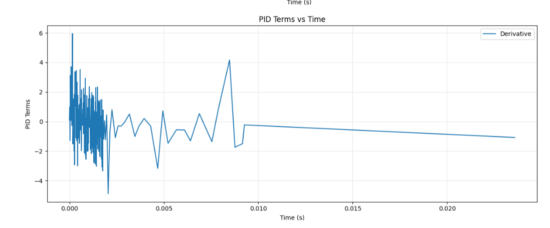
Since I am integrating the gyroscope data to get the yaw estimate, it does not make sense to integrate the derivative term as well since it would be a more noisier version of the signal directly produced by the gyroscope Therefore, I took the derivative term away from this implementation of a controller. An example of the noisy derivative term is shown below.
Integral Control
To tune the integral gain and help close the steady-state error, I started with a small value of 0.001 and gradually increased it until I was able to get close to the target angle without overshooting. In the final implementation, the integral term is 0.002.
The final gain set up that worked for my system was Kp = 0.4, Ki = 0.00, and Kd = 0.002.
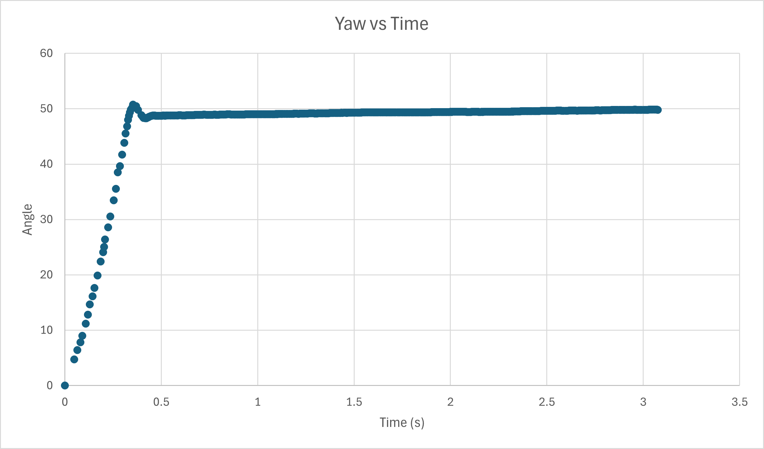
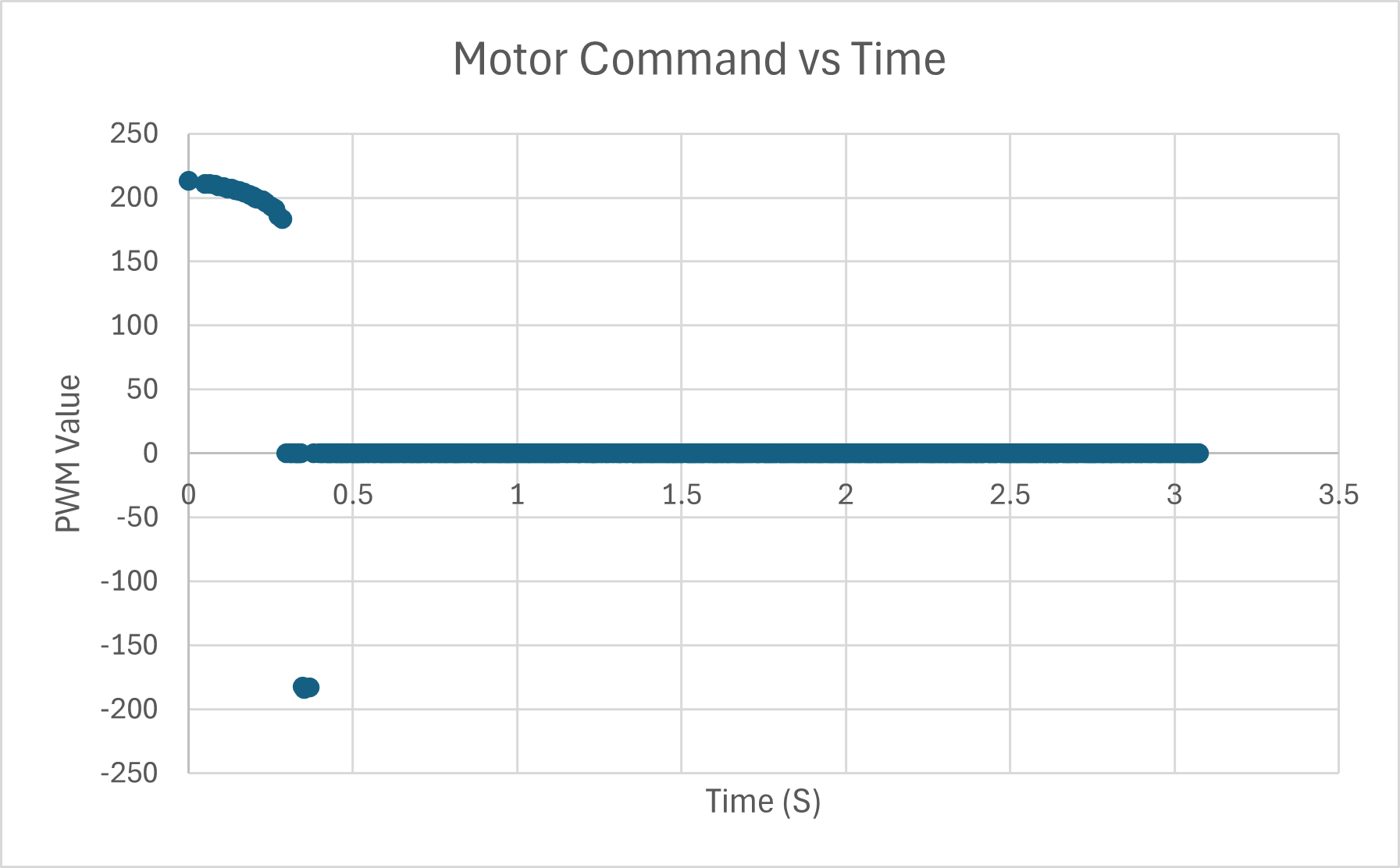
Test 1: 48 Degree Set point
Integrator Windup
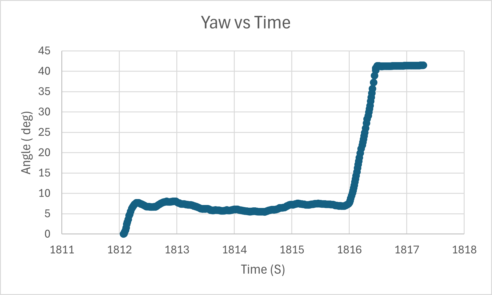
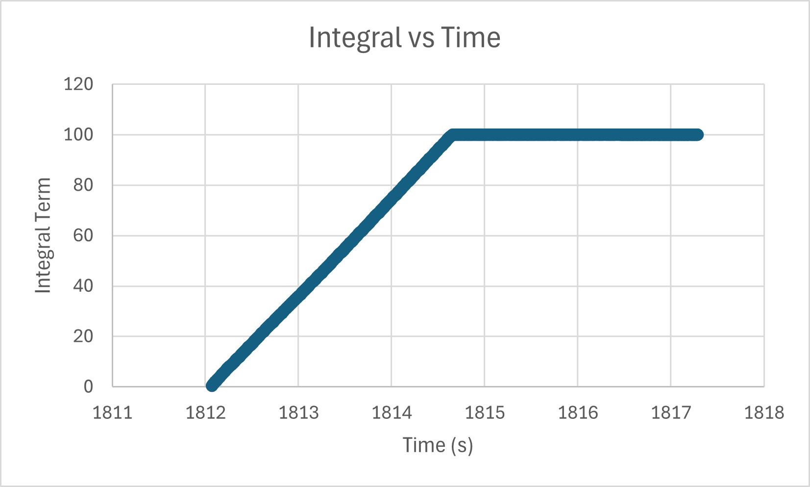
I implemented the integrator windup protection by constraining the possible value of the integral term as shown in the code snippet below. One reason for impelementing wind up protecting is to handle the scenario where the car is temporarily stuck or blocked by an obstacle. In such a case the integrator error would continue to accumulate while the car is not moving, resulting in a large integrator term that would be difficult to recover from. I tested the effectiveness of the protection by holdong the car in place for a few seconds and then allowing it to turn. The integral data shown below demonstrates the integral term being constraint to a max of 100, which is a value that I chose.
Artemis Code
Resources
I used Stephan Wagner's page as a resouce for seeing how to organize the PID controller code.