Lab 8: Stunts
Stunt Methodology
My approach to perfoming a flip was to drive the robot towards the wall at high speed and quickly reverse the motors to allow the robot's forward momentum to help it flip over. To aid the flip, I added a bag of coins to the front of the robot (seen in the image below) to shift the center of mass forward.
State Machine
I broke up the stunt sequence into 4 distinct phases: forward_approach, reverse_flop, orientation_control and continue_reversing. The transition from forward_approach to reverse_flip is triggered by the TOF sensor data, while the rest of the state transitions are controlled by timing. The full stunt code is available in the code section below.
FORWARD_APPROACH
In the forward phase, both motors are set to pwm value of 255 while the TOF data is monitored. The TOF threshold that triggers the transition to the reverse_flip phase is set to 530 mm instead of 304 mm to account for the added reaction time needed to reverse the motors. The value of 530 mm was experientally determined and tuned.
REVERSE_FLOP
During the reverse_flop phase, both motors are set to -255 pwm values for a duration of 260 ms. This duration was likewise tuned experimentally.
ORIENTATION_CONTROL
CONTINUE_REVERSING
In the continue_reversing phase, both motors are set to -255 pwm values for a duration of 500 ms in order for the robot to approximately its starting position.
Stunt Code
Artemis Code
Data Collection
I used two bluetooth commands STUNT, for starting the stunt sequence, and STUNT_DATA for transmitting the collected data. I used the same array data collection method as employed in all my previous labs, recording the TOF distance data,time, and motor command data during the stunt sequence. I also added an array for capturing the state of the stunt sequence denoted as 1-4 for the 4 phases of the stunt sequence. The logging code and the bluettoth commands are pictured below.
Trials
Trial 1
T1 Data
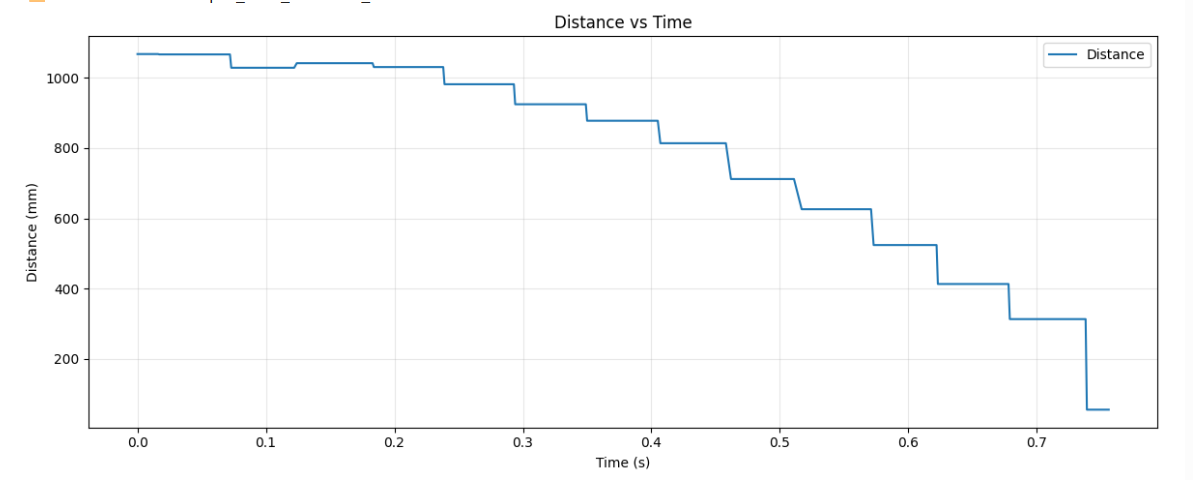
Time of Flight Distance Data
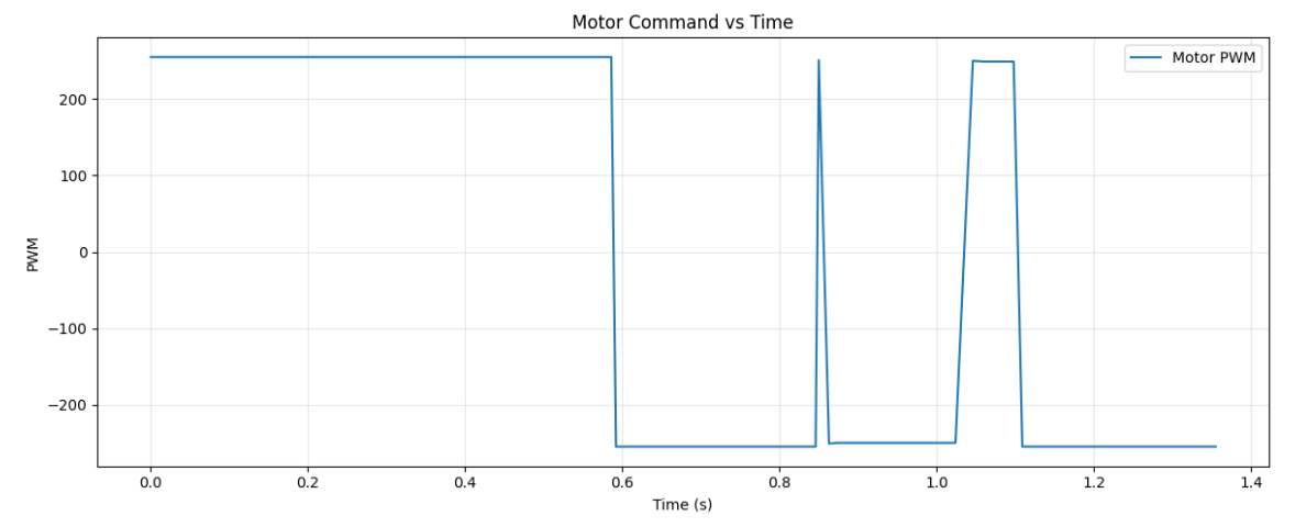
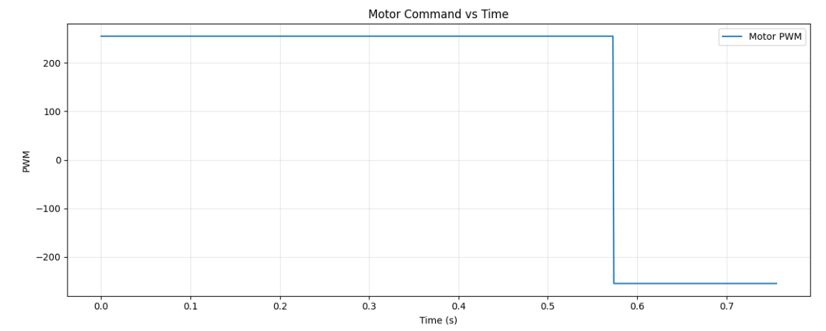
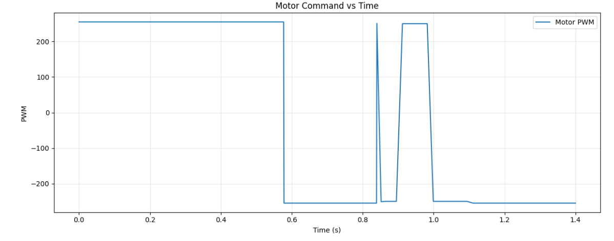
Motor Commands Data
State Transition Data
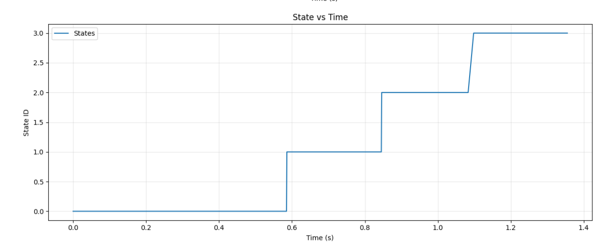
The above graph is one example of a state transition graph used for debugging the timing of state transitions. The values 1-4 correlate to the 4 phases of the stunt sequence.
Trial 2
T2 Data
Time of Flight Distance Data
Motor Commands Data
Trial 3
T3 Data
Time of Flight Distance Data
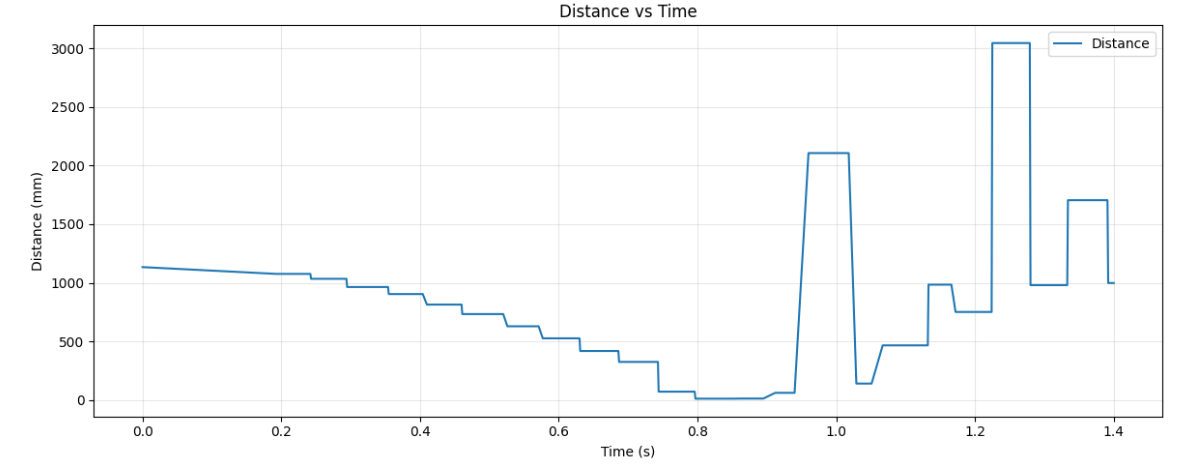
Motor Commands Data
Resources
I did not utilize any external resources for this lab.